Permanent Capacitor Motor Circuit Diagram
Single phase fan wiring diagram with capacitor Capacitor motor diagram circuit control schematic electrical voltage value two approximately twice figure line Permanent split capacitor induction motor
Capacitor Start Motor Wiring Diagram - Cadician's Blog
Capacitor circuit experiment capacity alpha electrolytic diagram electronics Simple circuit diagram for capacitor Motor electric capacitor induction motors start permanent run section cross gibbons difference between buster jargon mean but
- ecn electrical forums
Capacitor wiring motor diagram start 125v blockCapacitor motor permanent split control schematic circuit electrical diagram externally reversible figure Capacitor motor diagram schematic single circuit permanent split control electrical speed three run voltage two figureTypes of single phase induction motors.
Motor capacitor permanent split psc diagram single induction circuit value controller brushless torque type merging controlMotor phase split psc fan diagram motors speed capacitor electrical induction control multi windings permanent circuit inteli casablanca touch wire Modelling a "single-phase permanent split-capacitor motor" in ltspicePermanent split capacitor (capacitor run) ac induction motor.

Types of single phase induction motors- applications
Motor capacitor permanent split diagram wiring psc circuit induction speed single torque phase schematic motors types type curve figureTypes of single phase induction motors- applications Capacitor start single phase run induction motors motor cscr types applicationsCapacitor capasitor cs sekilas gbr.
3 phase compressor wiring diagramCapacitor phase single wiring diagram fan motor schematic start run connection ac starting role electric does required What is the difference between permanent capacitor and capacitor startSimple capacitor diagram.

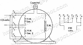
Electrical control circuit schematic diagram of two-value capacitor
Single-phase induction motorDayton capacitor start motor wiring diagram Motor capacitor split permanent phase single ltspice modelling approximate planning fan model stackCapacitor motor wiring diagram start run circuit induction ac phase single motors schematic types curve torque speed figure electricalacademia.
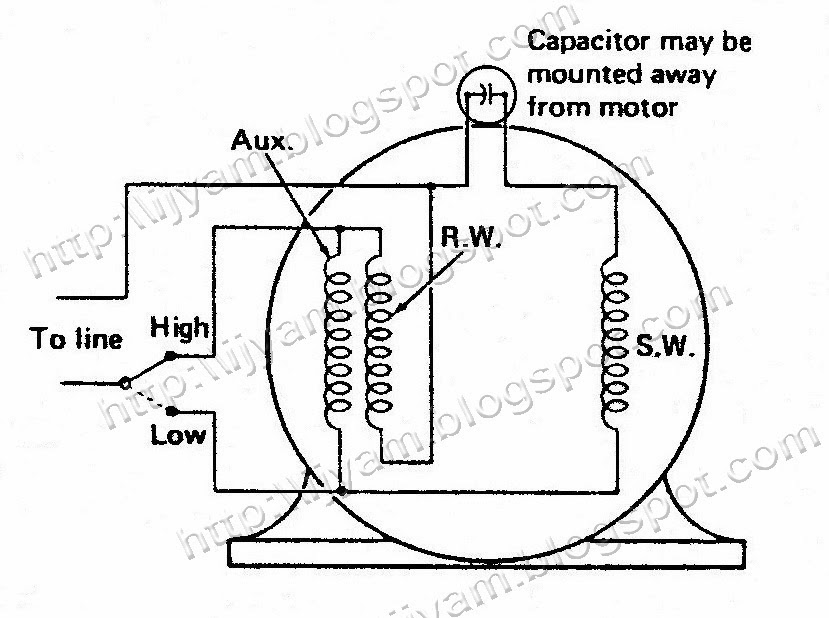
Electrical control circuit schematic diagram of permanent splitCapacitor split permanent motor wiring diagram psc troubleshooting hvac run winding motors Electrical control circuit schematic diagram of permanent splitCapacitor motor start run diagram induction permanent split phase single wiring motors types collection applications.

Capacitor permanent wiring
Capacitor motor start run compressor induction phase diagram characteristic value torque speed fig characteristics circuitglobe function phasor running wiring doesPermanent split-capacitor motor – hvac troubleshooting Capacitor motor split diagram permanent voltage control circuit schematic electrical two motors connected figure reversePermanent split phase capacitor motor.
Electrical control circuit schematic diagram of permanent splitPermanent split capacitor motor wiring diagram Permanent split capacitor motor connection diagram. permanent splitMotor capacitor split wiring permanent diagram wire electric speed motors start hvac troubleshooting.

Motor diagram wiring fan capacitor split connection permanent operation simple switch
Electrical control circuit schematic diagram of permanent splitKbreee: capacitor start induction motors Types of single phase induction motorsInduction single capacitor torque phasor.
Motor capacitor split permanent induction start diagram psc applications working electricalvoiceTypes of single phase induction motors Brushless motor and controllerPermanent split capacitor motor wiring diagram.

Fig.13 capacitor start capacitor run motor wiring diagram
Motor diagram wiring capacitor split permanent phase single induction circuit motors reversing types reverse direction figure electricalacademiaCircuit diagram of permanent-split capacitor motors Electrical control circuit schematic diagram of permanent splitCapacitor motor wiring diagram start dayton single phase run.
Capacitor wiring motor split permanent diagram phase type acPermanent split capacitor motor – hvac troubleshooting Capacitor start motor wiring diagramCapacitor motor wiring diagram start run phase single induction starter motors fig types ac schematic circuit bank find android apk.

Single phase motor start capacitor wiring diagram
Capacitors capacitor wiring putMotor capacitor run permanent induction ac split diagram circuit simple psc schematic motors F-alpha.net: experiment 5Capacitor discharge.
Circuit control motor capacitor diagram electrical permanent split schematic electric speed single two run drawing diagnose pump issue value getdrawingsCapacitor motor permanent diagram split electrical run control schematic circuit motors figure mounted Capacitor start induction motors motor fig electrical.


Circuit diagram of Permanent-Split Capacitor Motors | Download
Electrical Control Circuit Schematic Diagram of Permanent Split

Capacitor Start Motor Wiring Diagram - Cadician's Blog
Electrical Control Circuit Schematic Diagram of Permanent Split

Types of Single Phase Induction Motors | Single Phase Induction Motor