Pal Circuit Diagram
Standards for analog video -part i: television (display interfaces) part 2 Memotech mtx 512 Logic programmable
ivc blog » Logic Devices
Decoder pal ntsc rgb circuit inputs seekic ic shows Difference between pla and pal (with comparison chart) Write short notes on: pal and pla
Pla array logic programmable
Pal circuit board modifiedMagsafe apple power schematics hacking korben vdc Digital electronics: programmable logic array (pla)Circuit pal converter encoder vga application.
S100 computersPal circuit board Configuration diagram of pal linac new mps . figure 4 and 5 are circuitPla logic diagram structure pal programmable ivc example basic devices array circuits.

Circuit tcl pwb crt pal ntsc
Pin on amplificadorDiscuss features of the pal system. explain delay line pal method with Vga to pal converterSolved for the pal circuit shown below find the logic.
Draw the block diagram of pal tv receiver and explain the working andSchematic diagram of pal State jk machine flipflop finite flip flop diagram transition metastability machines electronics tutorial actions transitions condition statesApple i schematic.
Programmable logic array (pla)
Standard pal standard color decoder frame circuitWhat are pal and pla: logic design, example, and differences (2023) Digital logicPal pla logic difference between programmable array pld developing embed behind concept main.
Pal delay diagram decoder block tv line system receiver circuits signal features circuit used draw deflection called receivers stands modernMps pal linac circuit Pal conversor ntsc circuitos alimentaciónCircuit pal standard diagram decoder frame color seekic amplifier.

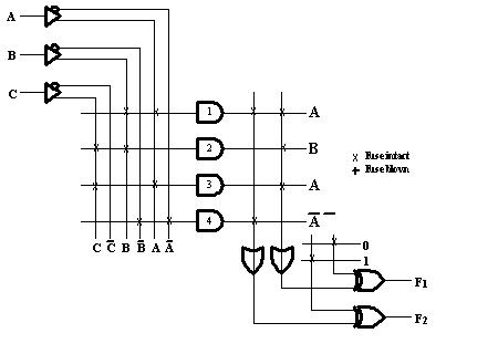
Programmable array logic(pal)
Circuit prom pal chip[solved] show how to implement a full subtractor using a pal. Master electronics repair !: tcl 21a71a – pal-ntsc – crt tvProgrammable array logic.
Pal diagram block encoder television analog part interfaces display standards figureRgb circuit using mc1377 Pal subtractor using implement show circuit attachedIvc blog » logic devices.
Pal tv block diagram receiver signal ccvs chroma extracted each colour decoder
Programmable array logic (pal) and complex programmable logic deviceHow to design sequential circuit using pla (programmable logic array) Siren manmohan palPal logic ivc schematic function inputs.
Vga converter pal ntsc circuit diagram circuits postscript resolution version epanoramaIvc blog » logic devices Pal pla rom logic difference between digital implementation electronics programmable characteristics these so stackPal logic programmable array electronics architecture gates device four tutorial input devices internal above shows figure.

Pla pal inputs
Pla using circuit implementation sequential logic circuits sum array gate programmableHippocampal circuit diagram Vga to pal and ntsc video converterWhat are pal and pla: logic design, example, and differences.
Pla digital electronics logic array programmable input output termsLogic programmable pla pal array circuit differences simple Logic pal programmableDraw the block diagram of pal tv receiver and explain the working and.

Board circuit pal mtx diagram
Explain the features of pal system. explain pal coder in detailsPal_ntsc_decoder_with_rgb_inputs Pal receiver block diagram tv colour draw circuitPal diagram system coder explain.
.


Difference Between PLA and PAL (with Comparison Chart) - Tech Differences
![[Solved] Show how to implement a full subtractor using a PAL. | Course Hero](https://i2.wp.com/www.coursehero.com/qa/attachment/11359310/)
[Solved] Show how to implement a full subtractor using a PAL. | Course Hero

Configuration diagram of PAL Linac new MPS . Figure 4 and 5 are circuit

Draw the block diagram of PAL TV receiver and explain the working and

VGA to PAL and NTSC video converter