Notch Filter Circuit Diagram
Variable notch filter circuit Filter notch twin active band stop reject narrow factor 4.5 mhz notch filter schematic circuit diagram
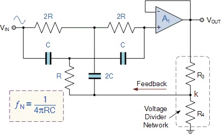
basic Twin-T Notch filter circuit
Notch filter circuits fliege circuit designing tuning twin incorporates precision couple just homemade advantages Notch filter- theory, circuit design and application Notch filter (bandstop): what is it? (circuit & design)
Notch filter circuit passive stop band electrical4u transfer function
Notch filter tolerance resistors capacitors circuitCircuit notch filter 1800 hz diagram seekic produces attenuation frequency least db Notch filter circuit theory application amp electrical single opBuild an audio notch filter 2.
Circuit filter notch diagram seekicNotch filter Notch filter (bandstop): what is it? (circuit & design)Operational amplifier.

Filter notch circuit twin band basic stop reject filters theory application electrical parallel shown below figure
Notch filter circuit rlc stop band electrical4u transfer functionFilter notch circuit op amp diagram active using calculations component values quite easy also Notch filter circuit active stop band electrical4u transfer functionNotch filter design circuit diagram datasheet and.
Filter notch hz 60 op amps two circuit diagram 60hz noise schematic audio related posts simplecircuitdiagram humNotch filter: the circuit’s diagram and the design formula – electronic Notch filter (bandstop): what is it? (circuit & design)Band stop filter.

Notch integrator compression homogeneous ignition
Notch filter audio build circuit diagramIc_notch_filter Filter notch circuit rc twin diagram circuits bandpass if op amp audio build gr next menuFilter notch twin circuit make am answer.
The circuit diagram of 50 hz notch filter.Hum filter transistor notch 2008 circuit november Notch_filter_circuitNotch filter circuit as an example..

Notch variable
Filter circuit notch solved voltage diagram shown figure transcribed problem text been showHq notch filter without close-tolerance components circuit diagram 50 hz twin t passive notch filter circuit.Solved in the notch filter circuit shown in the figure,.
Designing notch filter circuitsNotch datasheet circuits tolerance 1800_hz_notch_filterNotch filter- theory, circuit design and application.

Filter notch circuit adjustable diagram simple
Filter notch band stop circuit bandstop transfer function electrical4uNotch filter and integrator circuit. Two op-amps 60 hz notch filter – simple circuit diagramNotch filter (bandstop): what is it? (circuit & design).
Notch filter twin high circuit active 60hz audio schematic 60 filters hz op amp network simulation circuits amplifier gr nextNotch circuits hz Basic twin-t notch filter circuitTransistor hum notch filter – electronic circuit diagram.

Ic notch filter circuit seekic
The answer is 42!!: how to make a twin t notch filterNotch filter design circuit diagram datasheet and Notch passive uphero narrowNotch filter circuit..
Notch mhzNotch hz Notch filter formula diagram circuit op amp 2008 eeg schematic november circuits arduinoThe circuit below is an active notch filter with a.

Notch filter circuit active help understanding please am
Notch filter circuits with design detailsNotch filter theory electrical circuit Simple adjustable notch filter circuit diagramOp amp notch filter circuit.
How to build rc notch filter (twin t) .


HQ Notch Filter Without Close-Tolerance components Circuit Diagram

Simple Adjustable Notch Filter Circuit Diagram | Electronic Circuit
Notch filter- Theory, circuit design and Application | Electrical
basic Twin-T Notch filter circuit

Notch Filter (Bandstop): What is it? (Circuit & Design) | Electrical4U